Gemini front end

The Gemini front end system, similar to other high power lasers, has MOPA (Master Oscillator – Power Amplifier) architecture. This means that a low energy, high-quality pulse is generated at the start of the laser chain and amplified to successively greater energies in a sequence of amplifiers. The source pulses are extremely short, so the technique of chirped pulse amplification is used to avoid distortion of the pulses and damage to the laser during amplification.

You may hear Gemini’s front end and Target Area 2 (TA2) being referred to as “Astra”. This is because Gemini was built upon a pre-existing CLF laser facility called Astra.

The front end consists of an ultra-short pulse oscillator that provides low-energy, high-quality seed pulses of around 12fs duration. These are slightly stretched to around 7ps in a glass block before being amplified to millijoule energy in a kHz repetition rate preamplifier. After the preamplifier, individual pulses are selected by a fast Pockels cell at a repetition rate of 10Hz.

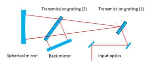
A much greater stretch is then applied, using a wavelength-dependent optical delay line. If the pulse is destined for Target Area 2 (TA2), it is stretched to 530ps, or if it is destined for Gemini, it is stretched to 1060ps. Pulses of this length can be amplified to multi-joule energies without reaching intensities that would damage optical components or cause severe distortion of the pulse. If the pulses were amplified without stretching, the resulting intensity could severely damage or even shatter optical components in the laser.

Three amplifiers are used in sequence to reach a final energy of more than 1J per pulse. Each amplifier consists of a titanium-doped sapphire (Ti:S) crystal that is pumped by pulses of green light from another laser. The green light excites the titanium ions in the crystal to a state of higher energy, a condition in which they are able to amplify the infrared light in the stretched seed pulse as it passes through the crystal.

All these lasers run at 10 pulses per second and are accurately synchronised so both the pump and seed pulses arrive at the crystal at the correct times. At the output of the third amplifier, the beam with the 10Hz pulse train is separated into two beams each with a 5Hz pulse train. One beam is sent to the Gemini laser area, and the other to TA2. Attenuators are used to control the pulse energy in each beamline. For TA2, a fast-acting mechanical shutter allows the experimenters to use either the full pulse train for setup and alignment, or to select individual full-energy pulses on demand.

To aid alignment of the pulse compressors, a dual-wavelength continuous wave (CW)  diode can be injected into either beam line at wavelengths of 785nm and 810nm. These are near the extremes of the pulse spectrum. Used in conjunction with alignment mirrors and imaging, the dual-wavelength beam allows the grating alignment in the pulse compressors to be optimised rapidly.

In the target area, the pulses are recompressed in vacuum to a duration of about 40fs before use. Pulses can be used at repetition rates of up to 5Hz at full energy, or at 10Hz with low energy for alignment purposes.​​

Gemini front end oscillator​

The oscillator is a commercial product made by Femtolasers. A titanium doped sapphire (Ti:S) crystal is pumped by 5.5W of 532nm green light from a frequency-doubled, diode-pumped neodymium vanadate (Nd:YVO4) laser.

Gemini oscillator

When mode-locked, the oscillator generates pulses of 12fs duration with a bandwidth from 750nm to 850nm, at an average power of 550mW. The repetition rate of the oscillator is 75MHz, which corresponds to a train of pulses 13ns apart, or one every 4 metres. Special dispersion-compensating mirrors are used within the laser cavity to control group velocity dispersion and keep the pulse length short.

The oscillator pulses are stretched to a few picoseconds in a glass block and then sent to the preamplifier. This is a Femtopower Compact Pro, a 9-pass Ti:S amplifier pumped by a kilohertz frequency-doubled, diode-pumped neodymium YLF laser system (Thales JADE 2). In the preamplifier, one oscillator pulse is amplified every millisecond to an energy of 800mJ; the remaining pulses do not get amplified and are rejected from the pulse train at the next stage.

The train of amplified pulses at 1kHz repetition rate passes through a pulse selector consisting of a fast Pockels cell and polarisers. This diverts every hundredth pulse into the beam path leading to the laser to make a 10Hz pulse train that seeds the rest of the amplifier chain.

Pulse stretcher

Two gratings and spherical mirror comprising the Gemini pulse stretcher.

The ultrashort pulses produced by the oscillator cannot be amplified directly to high energy. A pulse of 12fs duration with an energy of a few tens of joules would have such a high intensity that it would cause electrical breakdown as it passed through solid materials, and would suffer significant distortion even while propagating through ordinary air. This would lead to significant damage of optical components in the laser chain.

To avoid this, almost all high-intensity short-pulse lasers use “chirped-pulse amplification”, a technique where the short pulse is stretched by a factor of many thousands before amplification. This keeps the intensity in the stretched pulse low enough to avoid damage and distortion on its journey through the laser system until the final moment when it is recompressed in a vacuum to its original duration before being focused onto a target.

The pulse stretcher is a wavelength-dependent delay line based on diffraction gratings. The effect of the stretcher is to delay the shorter wavelengths more than the longer ones, resulting in a stretched pulse with a 530ps time duration from start to finish. This is 44000 times longer than the original oscillator​​ pulses, and the peak intensity of the pulses is reduced by the same factor.

In 2014, the original stretcher was replaced by a new version that uses transmission gratings. Studies of the contrast of the Gemini pulses had revealed that the large grating in the pulse stretcher was a factor in generating a contrast pedestal in the compressed pulses. Offline tests showed that the pedestal was reduced by more than a factor of 10 when transmission gratings were used in the stretcher. The new stretcher had better throughput than the old one, and there was an improvement in the pulse contrast.

Ray diagram showing a pair of Gemini gratings used to stretch a pulse by putting different wavelengths of light in different places in time.

At the end of the laser chain, another pair of diffraction gratings is used to reverse the effect of the stretcher by delaying the longer wavelengths more than the shorter ones, thereby compressing the pulse to its original length.

Amplifier one

The first power amplifier receives the pulses after they leave the stretcher. A 10mm thick, 10mmdiameter titanium-doped sapphire (Ti:S) crystal is pumped on both sides with a total of 90mJ of green light from a frequency-doubled Q-switched Nd:YAG laser. The pulse is sent through the crystal four times, reaching a maximum output energy of 4mJ after the final pass. After amplification, the beam is spatially filtered to smooth its intensity profile and then expanded to 6mm diameter. At this point, a Pockels cell between a pair of crossed polarisers is used to minimise the amount of amplified spontaneous emission (ASE) transmitted to the second amplifier.

Gemini green pump laser for amplifier one.

Alignment

The alignment of Amplifier 1 is controlled by an automated system in which the beam position is monitored at key points by cameras. The measured spot positions are analysed in software, and the data is used to control piezoelectric actuators on some of the mirrors in a closed-loop servo configuration. This ensures that the alignment of the amplifier and stretcher remain consistent throughout the day, compensating for changes that occur as a result of temperature variations in the room.

Improving performance

Amplifier 1 was rebuilt to improve its performance, in particular to eliminate internal reflections in optics that were degrading the temporal contrast of the compressed pulse. Double reflections in plane-parallel optical components propagate in the same direction as the main pulse and can give rise to contrast problems. To eliminate these effects, wedged components and Brewster angled windows were used wherever possible. In the new design the spatial filters, that provide image relaying between passes, use Brewster windows for minimum reflectivity, and the Ti:S crystal has a 10 arcminute wedge between its faces. The orientation of the beam is controlled so that the wedge does not introduce any overall angular or spatial dispersion in the beam.

Amplifier two

The second power amplifier is arranged in a “bow-tie” configuration, in which the beam path takes the pulses through the crystal four times. The crystal itself is a 10mm thick piece of titanium-doped sapphire (Ti:S), pumped on both sides by 300mJ pulses of green light from a frequency-doubled Q-switched Nd:YAG laser. The pump beams are image-relayed from the source to give a 6mm diameter gain region with a uniform intensity profile. The infrared pulses are amplified to an energy of 120mJ in this amplifier. After amplification, the beam is expanded to 18mm and apodized to give a quasi-flat-topped beam profile.

Gemini green pump laser for amplifier two.

Providing a plasma diagnostic beam line

After expansion, part of the beam (around 10%) is split off from the expanded beam to provide a probe beam for Target Area 2, where it is used to generate ultrashort optical pulses for probing the experimental plasmas. A small fraction of the split-off beam is also used to diagnose the main beam profile and focal spot at the output of the amplifier. The remainder of the beam continues to the third power amplifier.

Improving performance

Similar to Amplifier 1, Amplifier 2 was rebuilt to improve its performance, in particular to eliminate internal reflections in optics that were degrading the temporal contrast of the compressed pulse. Double reflections in plane-parallel optical components propagate in the same direction as the main pulse, and can give rise to contrast problems. To eliminate these effects, wedged components and Brewster angled windows were used wherever possible. In the new design the spatial filters, that provide image relaying between passes, use Brewster windows for minimum reflectivity, and the TiS crystal has a 10 arcminute wedge between its faces. The orientation of the beam is controlled so that the wedge does not introduce any overall angular or spatial dispersion in the beam. The beam splitter that provides the probe beam for the target area has a small wedge angle, and immediately following it there is a compensating wedge with an equal but oppositely-orientated angle, to eliminate angular dispersion that would prevent proper compression of the pulse.

Amplifier three

Gemini green pump laser for amplifier three.

The final amplifier has a bow-tie configuration, similar to Amplifier 2, that passes the infrared pulses through the gain medium four times. The titanium-doped sapphire (Ti:S) crystal in this amplifier is 24mm in diameter, 12mm thick and pumped by up to eight, frequency-doubled Q-switched Nd:YAG lasers, each capable of delivering up to 1.3J of green light. However, to reduce the risk of optical damage in the amplifier, the pump energy is restricted to a total of 4.5 joules. The beams from the four pump lasers are image-relayed to the Ti:S crystal, where they pump a region 18mm in diameter.

The Ti:S crystal is mounted in water-cooled housing to remove excess heat; the average power deposited in the crystal is 25 watts. There are vacuum spatial filters after the first and third passes of the crystal, to clean up the spatial profile of the beam and provide image relaying. The infrared pulses are amplified to an energy of around 1.2J in this amplifier.

After amplification

Rotating waveplates

After the amplification process, the beam is expanded to 31mm in diameter in a beam-expanding telescope. At this point, a rotating half-wave plate and a polariser sends the pulses alternately to Target Area 2 (TA2) and to Gemini. The waveplate rotates continuously at a rate of 1.25 revolutions per second, or 45° every tenth of a second, so if one pulse has its polarisation flipped by 90°, the next will be unaffected. The polariser after the waveplate reflects one polarization and transmits the other, thus sending a 5Hz pulse train to each area. The rotation of the waveplate is synchronised to a 5Hz trigger signal derived from the 10Hz rate of the Gemini front end.

Delivering laser shots to the target areas 

The energy in each beam can be controlled by means of slide-in attenuator mirrors that have 1% transmission, plus a combination of a rotatable waveplate and polariser that provide variable attenuation over a range of 100:1. An expanded continuous wave (CW) diode beam, used for pre-shot alignment, can be injected into the beam to TA2 via a slide-in mirror. Attenuated pulses at 5Hz can also be used for diagnostics set-up and alignment if required. Shots fired at full energy are restricted to 1Hz and for safety there must be nobody in the area when full energy shots are fired. A fast electromechanical shutter in the beam allows single pulses to be admitted to the target area on demand when the fire button is pressed in the control room.

Super intense Gemini beam 

The beam path to Gemini has a similar set of attenuators, so that the energy levels associated with each power mode of the laser are the same in both Gemini target areas. The Gemini beam travels in a vacuum pipe in a trench under the floor and is image-relayed with an expansion to 50mm diameter by the time it enters the Gemini laser hall.

Automatic alignment system

The new front end has very long optical path lengths distributed over two optical tables. These factors are detrimental to the stability of the beam alignment and make it prone to the effects of temperature drifts. For these reasons, this section of the laser chain was chosen for the deployment of the first part of an automatic beam alignment system.

A motorised mirror mount.

The system operates in a similar way to an adaptive mirror. The beam position is monitored at several key points by digital CCD cameras that image the beam profile viewed through the back of a mirror. The software controlling the system calculates the centroid positions of the acquired images. If the beam position differs significantly from a predetermined set point, the beam is steered back by means of motorised actuators fitted to mirror mounts located upstream from the cameras.

Operating the actuators in pairs ensures that the downstream beam path is fully defined, both in terms of position and direction. For applications where the pointing direction is more important than the beam position, a far field rather than a near field image can be used. For example, if the beam is focused onto the sensor, picomotors were preferred over other actuators like stepper motors or piezo stacks because of their compactness, their relatively low cost, and the fact that they hold their position when not powered. The system is currently using 13 cameras and 13 controlled mirror mounts.

The system is currently using 13 cameras and 13 controlled mirror mounts.

Technical Information about the corrections:

The control software acquires the camera images, calculates the centroids of the beam positions inside a certain region of interest, compares these positions to pre-determined set point values and finally

applies the necessary corrections to the Picomotors. The set of corrections for all motors is calculated as the product of a vector of the measured deviations and a control matrix. Mathematically, the control matrix is the pseudo-inverse of the response matrix, which contains the deviations induced on all cameras by moving each motor by a unit amount. This matrix-based approach enables all corrections to be carried out at the same time rather than having to carry them out sequentially, mirror-by-mirror.