Gemini is a petawatt-class laser with two target areas. It is named after the twin-beam setup that supplies one of its target areas.
Before its conception, Gemini’s front end and Target Area 2 (TA2) was originally a facility called Astra with two amplification stages leading to its target area. When it was absorbed into Gemini, a third amplification stage was added consisting of a pair of titanium-doped sapphire (Ti:S) crystal amplifiers, each with their own pump laser and pulse compressor.
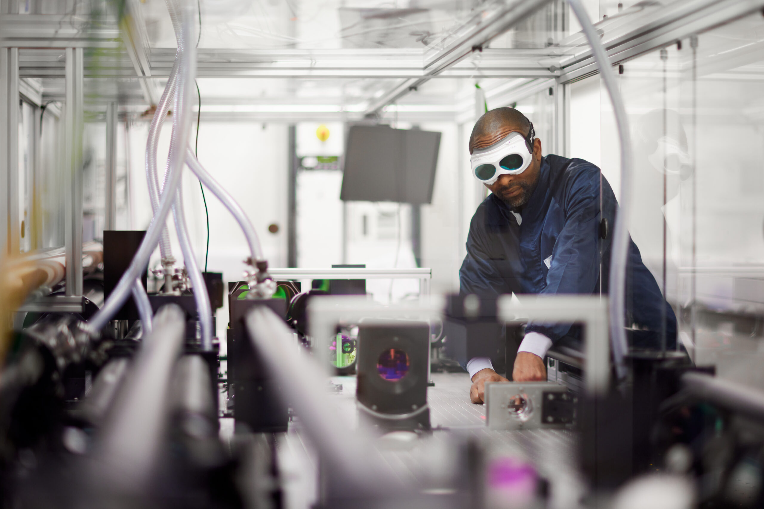
Gemini laser area 3
The two-beam design of Gemini was chosen to maximise the flexibility of the laser system and therefore the range of experiments that can be performed. Having two beams allows for combinations of long and short pulses, different focal lengths, variations in relative timing and mixed polarisations.
Each beam delivers 15J to target in a pulse of 30fs (a peak power of 0.5PW), with a maximum focused intensity of order 2 x 10^21 Wcm^-2. Gemini has a shot rate of once every 20 seconds, which is an extremely high shot rate for such a facility, and has allowed for new experimental approaches to ultra-high intensity physics research.
Another novel feature of Gemini is that the laser room is a floor above the experimental area, meaning the beams come down into the target chamber from the ceiling. This provides 360° access around the chamber and allows the beams’ polarisations to be controlled by the direction they are steered.
Gemini Laser Area
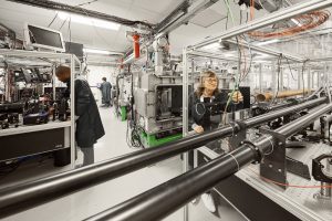
The Gemini laser area is on the floor above the experimental area, and contains the two amplifiers, their pump lasers, the two pulse compressor chambers, optics to split and direct the input beams, and a suite of diagnostic instruments.
The experimental area lies directly below the pulse compressors, so the output beams can be sent down vacuum pipes through holes in the floor to the target chamber below. The walls of the experimental area are made of 1-metre-thick concrete to provide radiation protection. The main optics tables in the laser area are positioned above the thick walls to ensure the best possible stability.
The source beam for Gemini travels almost 40m between the final amplifier of the Gemini front end and Gemini. Along that path, it is expanded from 31mm to 50mm in an image-relaying beam telescope which preserves the beam profile.
Gemini laser area 3
Shortly after entering the Gemini laser area, the beam is split into two halves. Each half is directed to a separate amplifier table. The relative timing of the beams can be set at this point, which allows the beams to reach the target area simultaneously or with variable delay. This flexibility allows for changes in the optical layout in the experimental area.
Both beams make four passes through a titanium-doped sapphire (Ti:S) amplifying crystal located on each amplifier table. The pump laser for each amplifier is a two-beam commercial Nd:glass laser (Quantel SA, Paris), delivering a total of 60J of second-harmonic green light at 527nm. These beams are homogenized using custom-made diffractive optical elements, which convert the non-uniform beam from the laser into a smooth top-hat profile of the correct size, with little loss of energy. Between successive passes there are image-relaying vacuum spatial filters to preserve the beam profile and minimise the growth of small-scale modulations. After the final pass, the pulse energy can be as much as 25 joules. This beam is expanded to a 150mm diameter in an achromatic expanding telescope, then sent to the pulse compressor.
The pulse compressor consists of two gratings and the retro mirror, and is located in a 3.5 x 1 x 1.25m vacuum chamber. This also contains three steering mirrors, which send the beam to the experimental area. All these optics and their mounts are supported on two solid aluminium breadboards, which in turn are supported on pillars fixed to the floor of the area. The pillars are mechanically isolated from the stainless-steel vacuum chamber, so the optics do not move when the chamber is pumped down.
Each chamber has its own turbomolecular pump, with a backing pump in the laser services area on the ground floor. The two compressor chambers and the interaction chamber share a common roughing pump, so only one can be pumped from atmospheric pressure at any time. As the compressors normally remain under vacuum for long periods, this does not cause any operational difficulties.
The final element in the laser area is the beam diagnostics table. Samples of the compressed beam leave the compressor chamber through windows and travel to a suite of diagnostics. There is a full-aperture beam transmitted through the final turning mirror, and a 15mm beam that has passed through a hole in the final mirror, and is therefore a true sample of the compressed pulse. The full-size beam is stretched by its passage through the mirror and large window, so is used for measurements that do not require a short pulse. It is telescoped down to a few mm diameter, and used to measure the energy, focal spot, and beam profile. The short-pulse beam leaves the chamber through a thin window, and is used for pulse length and contrast measurements, which can only be made with a short pulse.
Diagnostic information is captured on each shot and made available to the users immediately, as well as being archived.
Titanium-doped sapphire amplifiers
The Gemini amplifiers each have a titanium-doped sapphire (Ti:S) crystal 90mm in diameter and 25mm thick, significantly larger than those in the Gemini front end amplifiers.
The design of the amplifiers requires a small-signal gain of around 4.2 per pass to achieve the design output energy of 25 joules. Modelling of the performance showed that this output could be achieved with a total of around 60J of pump energy in a 50mm diameter beam, while keeping the energy density on the crystal at a safe level.
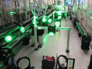
The gemini south amplifier showing various beam transport optics, beam tubes, and the Ti:Sa crystal. Green laser light can be seen from the pump laser.
A common problem with large-aperture, high-power amplifiers is that energy can be lost to so-called parasitic processes, in which the light emitted spontaneously in the crystal competes with the laser beam to extract energy stored in the pump region. The higher the gain along a particular path, the greater this loss becomes, and in some configurations the faces of the crystal can reflect enough energy back into the gain region for lasing action to occur; a so-called ‘parasitic oscillation’.
Several novel techniques were used in the design of the Gemini amplifiers to minimise these losses, which has ensured the amplifiers are efficient and behave as predicted. The most important of these was to specify crystals that absorb only 90% of the pump energy as it passes through. This leads to a fairly even deposition of energy within the crystal and avoids the formation of regions of very high gain at the crystal faces, which can cause the problems described. However, it would be wasteful to throw away 10% of the pump light, so the transmitted beams are returned to the crystal by mirrors, where a further 9% of the light is absorbed. In this way 99% of the pump energy is deposited as uniformly as possible in the gain region.
In addition to this, the crystal is mounted in a cell and surrounded by a liquid with a fairly high refractive index (1-bromonaphthalene) that has an absorbing dye dissolved in it. This traps the light that reaches the edge of the crystal and prevents it being scattered back into the gain region. Tests of the amplifier without the liquid present showed that this process caused the output to be clamped at a very low level, whereas when the liquid was added the performance of the amplifier agreed with the predictions of our modelling.
Output energies of 25J were measured with around 60J of pump energy, in good agreement with the modelling. At this energy, assuming a transmission efficiency of 60% in the compressor, which would be lower than average, the energy reaching the target area is 15 joules.
Gemini pulse compressors
The main optics of the compressor are the two gratings and a plane mirror.
The smaller grating is 320mm by 205mm, and the larger is 265mm by 420mm. Both are holographically generated with 1,480 grooves per millimetre and coated with gold. The plane mirror is coated with protected silver for increased reflectivity and damage resistance.
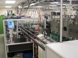
Gemini laser area 3 compressor chamber
The dispersion plane of the compressor is vertical, so the grooves lie in the horizontal direction, with the gratings tilted 36° from the vertical. The first grating is held with its face tilted downwards, while the heavier second grating faces upwards allowing it to be supported from behind. The mounts were designed to carry the load of the gratings while still permitting very fine adjustments to their rotations and position. Both mounts allow rotation of the gratings around horizontal and vertical axes (which intersect in the centre of the grating face), rotation of the grating in its own plane, and horizontal motion along the axis of the compressor.
High-precision bearing slides were used for all these motions, which are driven by stepper motors controlled by a driver program running on a PC in the laser area. The gratings are held in metal cassettes, which relocate into bayonet-type supports on the grating mounts. This allows the gratings to be covered while being installed and greatly increases the ease of handling, an important consideration given that the second grating in its holder weighs nearly 20kg.
The bandwidth of Gemini is around 35nm, which overfills the height of the second grating after dispersion by the first grating. This is why the compressor is operated in double pass, so the spatial dispersion of the beam in the first pass is reversed in the second. The return path is slightly offset from the input by a tilt of the back mirror about the vertical, so the compressed pulse is spatially separated from the input by a little more than a beam diameter.
The compressed pulse is steered to the final mirror, which sends the beam downwards into a vacuum pipe connected to the interaction chamber. The pointing of this mirror is controlled from the target area. At the top of the pipe is a gate valve to allow vacuum isolation of the compressor when the interaction chamber is at atmospheric pressure. The gate valve has a window so that low-power beams can be sent to the target area even when the gate valve is closed. There is a shutter inside the compressor chamber, which is closed when the beam is not required in the target area, and which carries a disc of absorbing glass to dump the energy when the beam is being used in the laser area.
To preserve the grating reflectivity, a radio-frequency cleaning system has been installed in each chamber, similar to the one in Target Area 2. An RF discharge in a low-pressure mixture of oxygen and argon creates oxygen ions, which attack carbon deposits on the grating surface and remove them as CO2 without damaging the grating rulings.